
New pedal build: MXR Distortion+ clone part 2
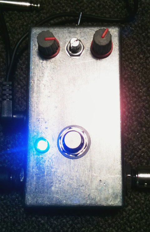
Here’s the modified Distortion+ circuit all boxed up with it’s additional controls.
One thing that I really wanted to add to the Distortion+ circuit was a tone control, and in my search for various modifications to the Distortion+ I found a great article from Premier Guitar written by Brian Wampler (of Wampler Pedals). I really found the article interesting, not just because of the modifications listed, but also the explanation of how the effect worked. I still cannot read schematics properly just yet, but I think I should be able to with a bit of research and practice.
I found a couple of modifications in this article I wanted to try out, the aforementioned tone control I was seeking, and the extra gain modification.
I tried the extra gain modification first, which consisted of replacing R2 with a 1K resistor and C3 with a 0.22uf for the same high gain frequency response but more gain potential. I didn’t have any 0.22uf capacitors, so I took two 0.1uf MKT capacitors and soldered them together in parallel to add the two values up to equal 0.2uf (here’s a good article on adding resistors and capacitors in series and parallel, and what happens with them). I figured 0.2uf was close enough to the original value required.

And it’s messy guts. Will be doing a refit with a neater layout.
This modification definitely gave the circuit more distortion, although at the highest ranges it took on a nasty boomy overtone on lower notes. I wasn’t entirely happy this so I decided to play around with a few more values.
I ended up settling with a 0.33uf MKT capacitor in place. In conjunction with the 1meg resistor it provided plenty of distortion, and the boomy notes were a thing of the past.
Adding the tone control involves removing the 0.001uf C5 capacitor, located to the left to the diodes on the strip board layout. The original modification listed the article earlier suggests putting a 0.022uf capacitor wired in series with a with a 1meg potentiometer. To wire this up correctly solder one of the capacitor leads to the top hole seen in the layout, and solder the other lead to a wire which will go to your 1meg potentiometer. Connect the wire to lug one of your pot, and then take another wire, and solder it across the remaining two lugs of the pot, and then connect it to one of the ground points on the circuit. This can actually be where the capacitor originally connected as it’s on the ground path.
I found the resulting modification gave the new tone control too subtle a range for my liking so I experimented with a few more capacitors that I had in my parts box. I ended up settling on a 0.1uf capacitor, which I felt gave me a broad range of tonal control, from very bass heavy and next to no treble or mids, through to a tone with little bass and lots of high end when using the silicon diode clipping. The LED clipping was still a little too thick and lacking high end though. I would like to try a higher value capacitor in it’s place but it will have to wait until I have some.
The next change I tried was replacing the standard LM741 op amp with a TL071. I was advised by a member at DIY Stompboxes forum that they had tried the TL071 and found it to have more clarity, but it was more more trebly and harsh. I figured that since my circuit now had a tone control the harshness could easily be taken care of by rolling the tone back a bit.
Plugging the pedal in with it’s new TL071 op amp I noticed that the pedal did in fact have a little more clarity, and had slightly more high end in the tone. The changed also quietened down the noise levels a little as well. The LED clipping was still too thick though, and the highest ranges of gain where too boomy on lower notes.
I needed to sort out the annoying high gain tone, and try to get the LED clipping sounding a less bassy, so it was back to the drawing board. I reinstalled the original R2 and C3 values just to hear the stock gain range again, and thought about what I could do to increase the gain range without getting the booming tone at higher levels.
To see what would happen I reinstalled the 1K resistor to R2, and left the original 0.047uf C3 capacitor. I plugged the pedal back in, and found that the gain range had increased, and the annoying boomy tones had completely disappeared.
At the same time I added a 1N4004 diode to the LED clipping side to see if I could get a more pleasing tone. The difference was amazing! I still retained the nice crunchy amp-like tone that LEDs are known for, but the addition of the silicon diode opened up the tone, adding more mids and high-end, as well as some more gain. This modified circuit was starting to sound really fantastic.
The high gain settings are beautiful now, searing distortion without the annoying buzz-saw tones that many high gain distortion pedals have. There are two distinctly different and usable tones available switching between the symmetrical silicon clipping and asymmetrical LED/silicon combo too.
This has been a really fun build. I’m planning on playing with the circuit a bit more to see if I can refine the higher gain levels a bit, as well as fitting the germanium diodes when they arrive. I think I’ll also go with a lower value potentiometer when I put together a better enclosure layout. Also I’m trying to come up with a name to suit it. So far I’ve got “Distortion++”, but I’m sure I can come up with a better name. If you have any suggestions post a comment!
Leave a Reply