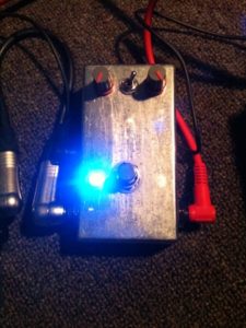
New pedal build: MXR Distortion+ clone part 1
Over the past few weeks I’ve been spending my spare time working on a new pedal build, my first using an integrated circuit (IC). The MXR Distortion+ circuit is a fairly simple circuit to build, using the LM741 operational amplifier (op amp), two diodes, and a handful of capacitors and resistors.
Like my LPB-1 build, I worked on strip board again, as I have quite a bit left over from the previous project. I used the same 1590B-style enclosure as well.
The bill of materials for this circuit is as follows:
- 2 x 1N4148 diodes (original Dist+ used Germanium diodes)
- 1 x LM741 op amp
- 1 x 8 pin IC socket
- 5 x 1Mohm resistors
- 2 x 10k resistors
- 1 x 4k7 resistors
- 1 x 0.01uf MKT capacitor
- 2 x 0.001uf MKT capacitor
- 1 x 0.047uf MKT capacitor
- 1 x 10pf ceramic capacitor
- 1 x 1uf 35V tantalum capacitor
- 1 x 1uf electrolytic capacitor
- 1 x 9mm 10k log (a) potentiometer
- 1 x 9mm 1meg reverse log (c) potentiometer
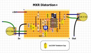
Building the circuit wasn’t too difficult, following a layout found at DIY Stompboxes. There was one issue though, the circuit didn’t work when it came to testing it.
Thankfully the people on the DIY Stompboxes forum proved to be of great assistance when I posted my help message on the forum. One observant member noticed that I was using a layout that in fact had an error on it. Thankfully a missing trace cut on the layout was all that was wrong, and with a correct layout provided I was able to get the circuit up and running.
Once up and running I noticed that my gain pot had a really off sweep, with the control ranging from no to minimal gain for most of the sweep, and the majority of the gain controlled by the smallest section of the sweep.
Thankfully the guys at DIY Stompboxes proved to be of help again, and informed me that I need a 1meg reverse log pot. for some reason I was using a 1meg linear pot. No idea why I had this listed in my parts list, but I have now ordered a bunch of 1meg reverse log pots from Small Bear Electronics, since my local store does not stock them. For the time being I’ve thrown in a 10K pot that seems to be handling the distortion duties quite well.
After building the initial circuit I decided to play with different clipping styles, so I added a DPDT switch so I could experiment with different types of diodes. I initially installed a pair of red 5mm diodes on one side, and the original 1N4148s on the other.
The 1N4148s provided a thinner, kind of fuzzy distortion tone which isn’t too bad for classic rock tones. The 5mm red LED pair boost the volume a great deal, and give an extremely thick, bassy chunky crunch tone which isn’t that pleasant with the tone of the pedal in a stock configuration.
I then threw in a pair of 1N4004 silicon diodes, and removed one of the LEDs to have an asymmetrical clipping setup. The LED clipping was slightly less boomy, but still quite thick.
I decided that I wanted have a setting on the pedal that sounded more like a stock distortion+, so I have ordered some Germanium diodes from DIY Stompboxes online store. I will install these on one side of the DPDT switch, and pick my favourite clipping type out of the others I’ve tried on the other side.
So far this has been a pretty good learning experience for me. I’ve been able to understand a little more about how basic circuits are working, and I’ve been able to get this pedal up and running far faster than my previous build.
Keep an eye out for part 2 of this build. I’ll be adding a tone control to the circuit, and trying to coax more gain out of the pedal as well.


Leave a Reply to Adil Cancel reply